
It can cause a tracking error in the PLL operation when the fundamental frequency changes to the different value of the constant angular frequency. However, the conventional SRF-PLL has a weak point of frequency tracking performance because it uses the constant angular frequency of a fundamental component. One of the popular PLL methods is synchronous reference frame (SRF-PLL) which uses a rotating reference frame for tracking a phase angle. The phase estimation, so-called phase-locked loop (PLL), is required to control the bidirectional ac dc rectifier especially, the phase information of supply voltage is mandatory to generate a current reference. The switching and the conduction losses in the bidirectional rectifier are the main cause of decreasing power conversion efficiency.

However, the unipolar switching mode rectifier using conventional switching devices including a normal antiparallel diode causes high reverse recovery current and turnon switching noise.

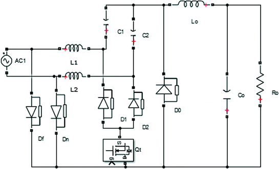
One of full-bridge rectifier legs in the unipolar switching mode is operated at a line frequency while the other one is modulated at a switching frequency. If the full-bridge rectifier operates in the unipolar switching mode, inductance for a continuous current mode (CCM) power factor correction (PFC) operation can be reduced. One of the disadvantages of the bipolar switching mode is the need of a large inductor to reduce the input current ripple because the peakto-peak voltage of the inductor is more than twice the unipolar switching mode. It has two sinusoidal pulsewidth modulation (SPWM) methods such as the bipolar and the unipolar switching modes. The single-phase nonisolated bidirectional rectifier typically consists of a conventional fullbridge structure. It usually consists of a nonisolated bidirectional ac dc rectifier for grid-connected operation and an isolated bidirectional dc dc converter to interface dc bus and dc link of the rectifier. In order to balance the power flow and to regulate the dc-bus voltage, the dc distribution system requires an isolated bidirectional ac dc converter to interface between dc bus and ac grid. The overall system configuration of the proposed 380-V dc distribution system is shown in Fig.

Especially, the dc distribution system for a residential house using dc home appliances can allow the flexibility of merging many renewable energy sources because most of the output of renewable energy sources is dc. INTRODUCTION DC distribution system is one of important future power systems to save energy and to reduce CO2 emission because it can improve the efficiency of systems due to the reduction of the number of power conversion stages. Keywords:- AC DC boost rectifier, bidirectional isolated converter, CLLC resonant converter dc distribution system. A dead-band control algorithm for the bidirectional dc dc converter is developed to smoothly change power conversion directions only using output voltage information. And CLLC resonant converter can operate under the ZVS for the primary switches and the soft commutation for the output rectifiers. PLL system shows lower detection fluctuation and faster transient response than the conventional techniques. In addition, the low-side switches are consisting of two MOSFETs to reduce the conduction loss in the rectification mode. Here the high-side switches of the ac dc rectifier employ IGBTs without anti-parallel diodes and SiC diodes. Zeba ahmed *, P.Purna Chander Rao ** *(Power Electronics, M.tech, JNTU university ** (Power Electronics, M.tech, JNTU University, Hyderabad Abstract The isolated bidirectional ac dc converter is for the 380-V dc power distribution system to control the bidirectional power flow and to improve its power conversion efficiency. 1 RESEARCH ARTICLE OPEN ACCESS High-Efficiency Isolated Bidirectional Ac Dc Converter for a Dc Distribution System Sk.


 0 kommentar(er)
